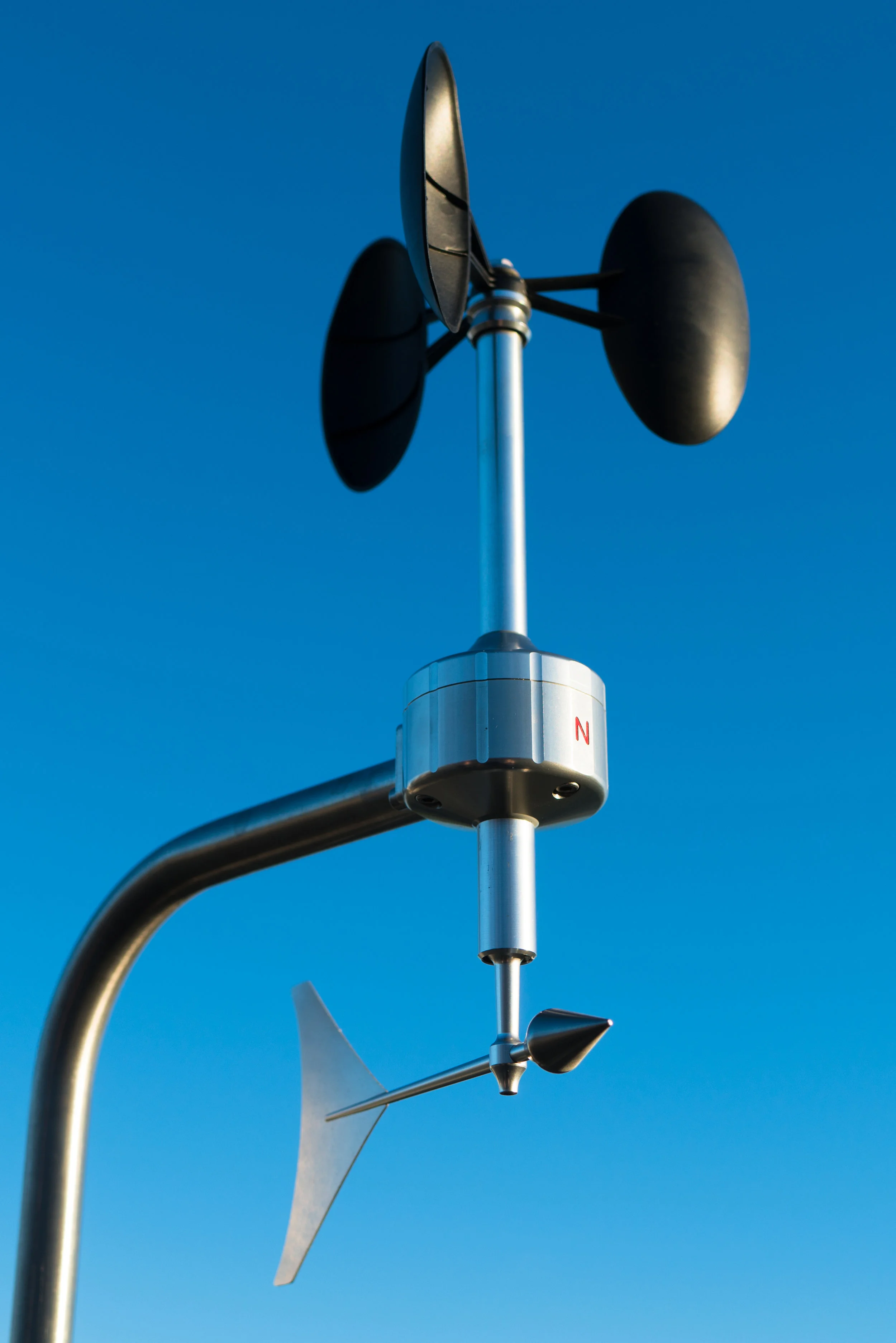
Thies Clima released their "First Class" Advanced X anemometer with MODBUS interface and 25W of body heating to join BARANI DESIGN Technologies MeteoWind® 2 as the only heated MODBUS anemometers on the market to meet MEASNET linearity requirements for wind resource assessment. While at first glance the new Advanced X seems similar to MeteoWind® 2, some significant differences remain.
MODBUS
BARANI DESIGN has been at the forefront of the adoption of robust and proven RS-485 MODBUS communication interface for the meteorological & wind resource assessment industries. Its anemometers and wind vanes have featured this common and highly reliable interface since 2008 and offer a very high level of data reliability and protection against lightning damage. Both companies incorporated user selectable MODBUS RTU and MODBUS ASCII protocols.
POWER CONSUMPTION & VOLTAGE RANGE
MeteoWind anemometers feature the lowest industry-wide power consumption of any MODBUS anemometer on the order of 4.5 mA for wind speed and wind direction combined. Thies Clima Advanced X anemometers have one of the highest power consumptions, averaging 40 mA and peaking at 100 mA, which is 10 x and 20 x higher than the power consumption of MeteoWind®. Advanced X anemometer voltage range is 3.7 V to 48 V while MeteoWind 2 range is 5 V to 24 V.
HEATING
Both anemometers feature 25 W of body heating, while MeteoWind® offers user selectable heating profiles for solar powered 12 V or 24 V applications where the heater can be controlled not only by the anemometer body temperature, but also by wind speed, thereby eliminating the need for intelligent heater control on the data logger.
WIND SPEED
Both anemometers feature optimized aerodynamics and mechanics for applications in high turbulence environments and feature minimal over-speeding, and very low starting speeds. Thies Advanced X has passed the full IEC 61400-12-1:2017 Edition 2.0 classification while MeteoWind® 2 full classification has not yet been performed. MEASNET calibrations of MeteoWind® 2 anemometers are performed on a regular bases per customer requests.
WIND DIRECTION
Only MeteoWind® 2 is able to meet MEASNET linearity requirements for wind speed while simultaneously and accurately measuring wind direction to better than 2° accuracy without a dead spot.
AIR DENSITY COMPENSATION
Thies Advanced X anemometer now features an internal air pressure sensor, while an air pressure sensor was last seen on the Elliptic Anemometer II, the predecessor to the MeteoWind® from BARANI DESIGN. Why did BARANI DESIGN remove the internal pressure sensor from its anemometers?
Aerodynamic effects are governed by the simple Reynolds number equation which, when applied to anemometer behavior, means that if an anemometer behaves linearly throughout the required wind speed range and beyond at one air density, variations in air density and air temperature will not affect its linearity and accuracy. Temperature will only affect bearing friction which at speeds above 4 m/s is negligible. In the case of an anemometers with body heating like MeteoWind® 2 and Advanced X, the air temperature effect becomes negligible throughout the whole wind speed range.
IS MEASNET/IEC 61400-12-1:2017 EDITION 2.0 NECESSARY?
Edition 2.0 for the year 2017 and beyond creates a new set of requirements for anemometer manufacturers to meet. But are these requirements just extra bureaucracy to fend off emerging anemometer competition or do they really help improve wind data quality over IEC 61400-12-1:2005 from the year 2005?
New requirement for 5 anemometers to be field tested. A larger sample size is always of benefit when compared to the IEC 61400-12-1:2005 requirement of field testing just a single unit.
The new requirement for anemometer wind tunnel testing at different densities and different air temperatures seems redundant when the MEASNET linearity requirement is already well defined and very strict. This new requirement is simply bureaucracy. Any aerodynamicist or just a student of basic aerodynamics should know and understand the simple and basic Reynolds Number equation governing the behavior of air. This understanding leads one to realize that, if an anemometer meets the linearity requirements of the original MEASNET IEC 61400-12-1:2005 without internal electronic corrections to its linearity behavior, than these new tests at different air temperatures and densities are completely unnecessary. Makes one wonder why Anemometer X now has an internal pressure sensor to enable corrections for air density and why MeteoWind® 2 is able to work just fine without it?


